About
2D & 3D Magnetic Field Simulation Modeling
State-of-the-art Risk Mitigation Technology
We provide plan-view and elevation view magnetic field simulation modeling of building electrical systems: Simulation modeling at a 50% and 75% building loads. These EMF simulation models illustrate the magnetic emissions profile as a 2D horizontal or vertical plane through the building. The sophisticated computer model calculates the magnetic emissions profiles as a function of magnitude and distance from the numerous electrical sources.

The computer generated building EMF simulation models can incorporate elements such as: transformers, switchboards, panels, feeders, automatic transfer switches (ATS) and more.
Source Modeling
Source modeling shows individual electrical elements and the potential impact on nearby sensitive EMI instrumentation and equipment. This type of computer modeling can assist in the placement for future equipment to optimize the use of building space and reduce the need for magnetic mitigation.

_
Electrified 50/60 Hz AC and 600 VDC Traction Current Simulation Modeling
Simulated future underground train and subway commuter tunnels can impact adjacent buildings with EMI sensitive instrumentation. The figure below shows a 25-0-25 kVA traction current underground catenary rail system emission profile.

The auto-transformer style traction system creates certain mitigation design challenges. The computer generated emission profile from the railway can be utilized to provide guidance to developers for placement of the railway to not only reduce electromagnetic interference for sensitive imaging equipment but also for human health purposes.
Electrified DC Third-Rail System
In addition to alternative current (AC) traction systems Vitatech also provides magnetic field simulation modeling of direct current (DC) traction systems. The figure below shows an elevated third-rail 600 VDC electrified train adjacent to a medical research building.

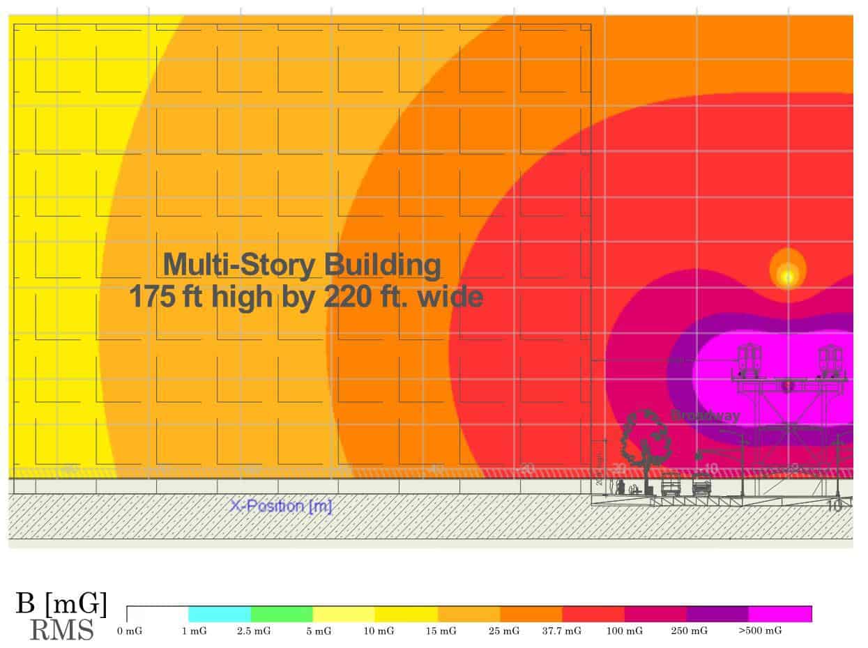
DC traction systems are typical in urbanized environments.
Simulations
Electric and Magnetic Field Simulation Modeling (DC to 500 Hz).
We use DC to 500 Hz electrified train and 50/60 Hz power frequency software to generate electric (E-field) and magnetic (H-field) simulated plots. Such power systems include: field plots of transmission and distribution lines, substations, transformers, primary and secondary feeders, network protector busses, switchgears, electrical panels, conduits/risers and electrified trains.
Utility, New Building & Renovation Modeling
50/60 Hz Magnetic Field Simulation Modeling of Utilities, New Buildings and Upgrades:
- Simulation modeling of External and Internal building EMI sources
- Implemented during Schematic Design and Design Development Stages
- Include mitigation guidelines such as, setback distances from EMI sources and magnetic shielding
- Define EMI instrumentation susceptibility limits
- EMF human exposure thresholds
- IEC EN 55035:2017 Immunity Standards for Multimedia equipment for computers, IT, broadcast receivers, audio & studio equipment
Electrified Train & Subway Modeling
We have modeled electrified, third rail and catenary AC/DC trains in Ireland, United Kingdom, Ottawa, New York and Boston.
RFI Modeling
We model antenna farms, cell towers, single and phased arrayed emitters, radars, microwave terrestrial and satellite communication systems. Field plots include electric field strength levels in V/m, specific absorption radio (SAR) in milliwatts per centimeter squared, and effective radiated power (ERP).
Finite Element
2D & 3D Finite Element Modeling (FEM).
Verify Shielding Design & Performance
Our software team of engineers and programmers use finite element modeling (FEM) software, to accurately solve 2-D & 3-D complex magnetic transient AC electromagnetic, magnetostatic and circuit modeling. To demonstrate our concept shield design, we simulated magnetic field emission models of AC ELF 50/60 Hz utility and building distribution systems and predicted shielding effectiveness based upon our recommended shield designs.


_
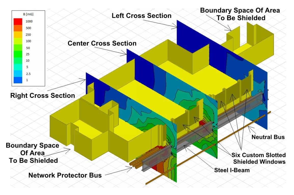
New York City Office Building above Network Protector Bus & Switchgear Room
3-D finite element model (FEM) simulation of energized network protectors, secondary feeders, and switchgear below a first floor office area. This FEM 2-D sliced 3-cross section simulation is similar to the actual recorded magnetic field levels of 198 mG RMS at 1-meter and 612 mG RMS on the floor.
_
After shield simulated models show 5 mG RMS or less compliance for human health exposure on the floor and at 1-meter.


_
BIM Magnetic Field Simulation – Revit & Voxler
Side by side FEM 3-D magnetic field comparison using ANSYS Maxwell and Surfer Voxler to simulate BIM EMF Modeling of unshielded and shielded MER with 75% energized transformers, network protectors, secondary feeders, switchgears, and distribution panels. Constructing electrical distribution model in ANSYS Maxwell, generating 3D simulation of 60 Hz magnetic field model, importing Maxwell 3-D with Revit/Navisworks building simulation models into Voxler to generate 3-D animation requires weeks of computational and programming time. Although the unshielded and shielded FEM 3-D animation looks impressive it is labor intensive to modify and implement small electrical and building design changes into the large and complex BIM model and re-simulate to generate another 3-D animation to evaluate EMI impact.
_
MRI, NMR and Ramping Magnet Isolines
Planning your facility around various MRI requirements can be challenging. Some MRI equipment manufacturers require that the MRI 3 or 5 gauss isolines do not intersect with adjacent MRI systems. Others recommend even stricter requirements. Medical industry protocol requires posting of 5 Gauss Warning Signs in public and patient areas where potential exposure to the MRI 5 Gauss isoline could compromise implantable devices. While this information is determined by closed bore or open bore superconducting magnets, EMI design criteria for building sites, health care centers, in-patient suites, triage centers and hospital testing equipment relative to the medical diagnostic instruments will minimize risks of EMI exposure.
To reduce the degradation of the MRI imaging resolution, prudent separation distance from busway/conduit risers, switchgears, transformer vaults, adjacent MRIs/NMRs, elevators, loading docks, trains or subways and more is highly suggested for long-term successful imaging quality and sensitive tool integrity.

Case Studies

30 Rockefeller Plaza
30 Rockefeller Plaza owned by NBC Universal and Tishman Speyer, is an eight decade...
Read More
Duke University Hospital
Vitatech was hired to assess the magnetic field impact from the primary electrical equipment...
Read More
King Abdullah University of Science and Technology
King Abdullah University of Science and Technology (KAUST) in Saudi Arabia is a 6.5...
Read More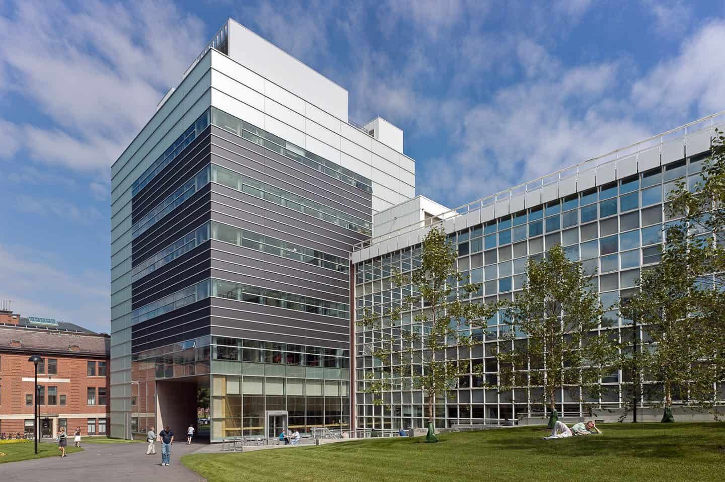
Harvard University
Vitatech was retained by Wilson Architects to perform an EMI/RFI assessment at the proposed...
Read More